Java is required for some animations on this website. Visit Java.com to download and install it.
The Standard
|
AS91170
Physics 2.3 Demonstrate understanding of waves 4 Credits External |
Assignments

Optics Assignment 1
|

Optics Assignment 2
|

Waves Assignment 1+2
|

Waves Assignment 3
|
The information in this page is presented to reinforce your understanding of physics concepts directly related to the above standard, and to provide additional resources to further your understanding in the field of waves and optics. As such, not all of the content below is assessed in the exam (some of it's just here to expand your mind!). This is noted in each section.
Wave Parameters (properties) - Assessed
Waves are produced by vibrations. A wave acts to transfer energy from one point to another without transferring matter.
The following video provides a concise introduction to wave parameters.
Waves are produced by vibrations. A wave acts to transfer energy from one point to another without transferring matter.
The following video provides a concise introduction to wave parameters.
|
|
|
The Electromagnetic Spectrum - Not assessed
Although not directly assessed in this standard, a basic understanding of the electromagnetic spectrum in a must for any aspiring physics student. The examples discussed in this video are often used as context in exam questions.
Although not directly assessed in this standard, a basic understanding of the electromagnetic spectrum in a must for any aspiring physics student. The examples discussed in this video are often used as context in exam questions.
|
|
|
Diffraction of waves - Assessed
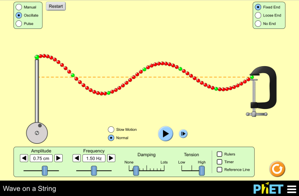
Diffraction is the spreading out of waves as they interact with the edges of a barrier or pass through a gap. The level of diffraction we observe depends upon the wavelength of the wave relative to the size of the barrier or gap. This phenomenon is often observed in our daily lives e.g hearing someone around a corner (before you can see them), wave patterns created by rock formations and harbour walls.
Diffraction is the spreading out of waves as they interact with the edges of a barrier or pass through a gap. The level of diffraction we observe depends upon the wavelength of the wave relative to the size of the barrier or gap. This phenomenon is often observed in our daily lives e.g hearing someone around a corner (before you can see them), wave patterns created by rock formations and harbour walls.
|
Click on the image to the left and work through the interactive animations and quizzes on all four pages.
Note the effect of wavelength on the extent of diffraction and hoe we use this to our advantage e.g VHF vs Long Wave radio. |
It is important to recognise in the diagrams below that the wave remains fundamentally unchanged as it undergoes diffraction. That is, speed, frequency and wavelength do not change (only direction). Your diagrams, in the exam, will need to be accurate enough to show this.
Interference ESA - Assessed
The principles and concepts of interference apply to both mechanical (water waves, sounds waves etc.) and light waves. The idea being that waves of the same kind can interfere with one another to either increase or decrease amplitude as shown in the diagram below.
The principles and concepts of interference apply to both mechanical (water waves, sounds waves etc.) and light waves. The idea being that waves of the same kind can interfere with one another to either increase or decrease amplitude as shown in the diagram below.
|
When two waves are in phase, they constructively interfere and the total amplitude is larger.
When two waves are 180 degrees out of phase, they destructively interfere and the total amplitude is reduced. |
|
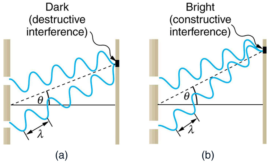
The path length from the two sources to the screen determines whether the waves will be in-phase or out-of phase.
Bright areas (antinodes) are formed when the difference in the two path lengths is a whole number of wavelengths. Dark areas are formed in the areas between the bright areas when the waves are one-half wavelength (180 degrees) out-of-phase. |
|
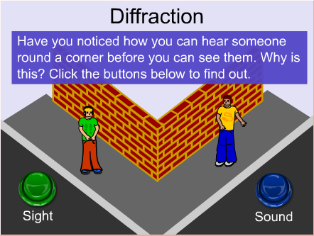
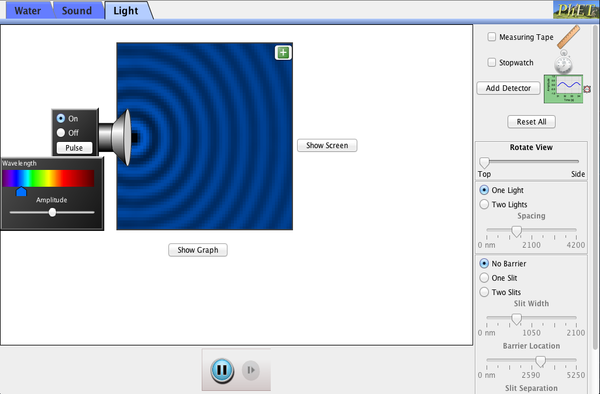
The first simulation allows you to investigate interference with different types of wave (click to download).
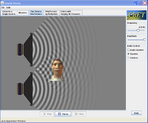
If you add two sources you will see an interference pattern. If you bring the two sources closer together, the antinodes are spaced FURTHER APART. If you increase the frequency (reduce the wavelength), the antinodes are CLOSER TOGETHER. The second simulation allows you to HEAR the effect of interference patterns from speakers. Try changing the spacing of the speakers and see what happens to the spacing of the antinodes. What happens to the spacing if you adjust the frequence of the sound? |
|
|
The famous Young's Double Slit experiment is explained quite nicely in this video. You can ignore the maths if you wish, as this is Level 3. You need to understand how interference causes the bright/dark fringes and how this relates to path difference (expressed in whole or half wavelengths). Incidentally, this experiment is also used to confirm that light can be both a wave and a particle at the same time!
|
Reflection of Light - Assessed
Although plane (flat surface) mirrors are not mentioned in the standard, a sound understanding of 'The Law of Reflection' is a must as it applies to all reflection boundaries (curved or flat).
Although plane (flat surface) mirrors are not mentioned in the standard, a sound understanding of 'The Law of Reflection' is a must as it applies to all reflection boundaries (curved or flat).
Curved lenses and mirrors
|
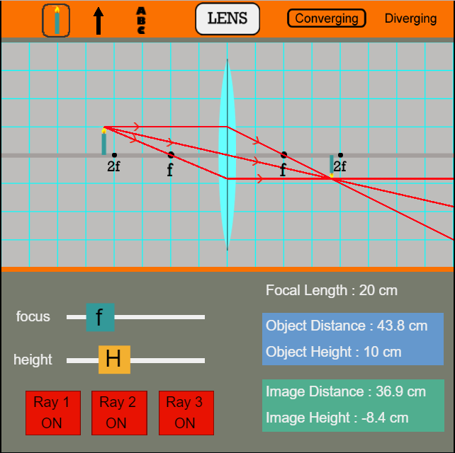
This interactive animation shows you how different types of images are created by different lenses and mirrors.
You can create a convex mirror (diverging) by dragging the object to the right-hand side of the mirror. |
The following set of videos deal with curved mirrors. They are composed by Doc Schuster, a Youtube legend (check out his channel). Some of the terminology and techniques used may vary from what we have done in class - don't let this confuse you.
|
|
|
|
|
|
Optical Illusions - Not Assessed (would be cool if they were though!)
|
|
|
Refraction of light - Assessed
The principles and concepts of refraction apply to both mechanical (water waves, sounds waves etc.) and light waves. Refraction occurs due to a change in speed when a wave travels between two different media (substances). If the incident wave strikes the boundary between these media at and angle to the normal, then a change in speed and direction will be observed. Note that speed and wavelength have in inverse relationship and, therefore, frequency remains unchanged.
The principles and concepts of refraction apply to both mechanical (water waves, sounds waves etc.) and light waves. Refraction occurs due to a change in speed when a wave travels between two different media (substances). If the incident wave strikes the boundary between these media at and angle to the normal, then a change in speed and direction will be observed. Note that speed and wavelength have in inverse relationship and, therefore, frequency remains unchanged.
|
|
|
In this course, you will be asked to solve problems relating to the refraction of light passing through curved lenses. There are two types of lens to cover.
Converging (convex) - light from a source will converge (focus) at a point (focal point) on the far side of the lens.
Diverging lens (concave) - light from a source will diverge on the far side of the lens as if it originated from a focal point on the same side as the source.
The videos below show you how to construct ray diagrams for each type of lens. Note that the terms used are different to what we use in class. All physics principals are the same, however.
|
|
|
Calculations will involve the use of Snell's Law (see p80 ESA) and Newton's or Descartes' formulas (the same formulas used with mirrors). Refer to your class notes for when to use negative values for virtual measurements, when applying Descartes' formula.
Total Internal Reflection (TIR) - Assessed
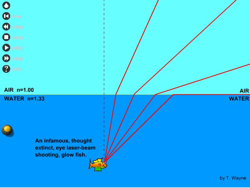
If light is travelling from a more dense medium to a less dense medium then the angle of refraction is always greater than the angle of incidence. As the angle of incidence is increased, it follows that the angle of refraction will, eventually, reach 90 degrees i.e. the ray of light will travel along the boundary. The angle of incidence at which this occurs is known as the Critical Angle.
If light is travelling from a more dense medium to a less dense medium then the angle of refraction is always greater than the angle of incidence. As the angle of incidence is increased, it follows that the angle of refraction will, eventually, reach 90 degrees i.e. the ray of light will travel along the boundary. The angle of incidence at which this occurs is known as the Critical Angle.
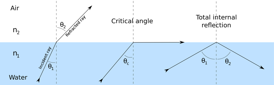
Note what happens in the diagram above when the angle of incidence exceeds the critical angle. The boundary now acts to reflect (not refract) the light ray and TIR is observed. Below is a mini-lesson from Kahn Accademy.
Interesting optics (Not assessed)
|
|
Watch from 12 minutes in to see how glass is an everyday miracle that has expanded our horizons.
|

